We take the particular case of a journal bearing shown below:
 |
</table style=”border:none;”>
|
||||||||||||||
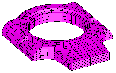
| Structural mesh of bearing housing |
| Fluid mesh of bearing film |  |
 |
 |
| Pressure contour field in lubricant film: crank angle = 300o | |
 |
|
| Lubricant film thickness: crank angle = 300o | |
| Applied journal loads v Crank angle |
A wide range of results are available for contouring and graphing, e.g. maximum pressure, minimum film thickness, journal power loss, journal eccentricities, etc.
 |
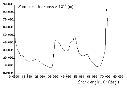 |
| Maximum oil film pressure v crank angle | Minimum oil film thickness v crank angle |
Pressures calculated by the PAFEC-EHL analysis of the oil film may be saved and subsequently back-substituted into the PAFEC-FE analysis of the bearing housing. Plots and graphs of deformations and stresses may then be viewed.
 |
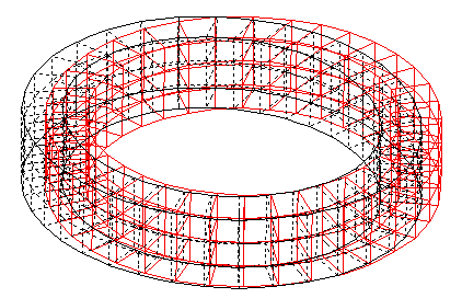 |
| Maximum principle stress for load step 55 in bearing housing elements adjacent to the oil film. | Deformation of housing elements adjacent to the oil film at load step 55. |